Alternative engine Golf GTI
Parts and tools required
A relatively simple swap is to go from WBX or diesel to I4 VAG group engines. These have been fitted to a bewildering array of VAG group vehicles and are available in many different flavours, most notably in this instance in 1.8 and 2.0 8V fuel injected configuration.
+ Fantastic parts availability, engines are cheap and robust, improved economy over WBX engines, conversions don’t need much in the way of custom parts, much keener to rev. - Not as smooth as a WBX, not as much low torque
I4 engines can be fitted using T25 Diesel mounting bars, waterpipes, sump, gearbox bellhousing, starter motor, oil pump pick up and clutch etc. A key issue in this conversion is the intake manifold – this fouls the chassis rail on a bus, when the engine is mounted at 50degrees. To get around this issue I recommend light impact adjustment on the chassis rail.
The installation is not difficult, but depends on what parts and facilities you have to work with.
Do you have the following from a Diesel T25?
Gearbox bellhousing; Bellhousing tinware; Starter motor; Mounting bars; Sump; Diesel input shaft, or grinder to cut the WBX shaft down; Waterhousings for head and water pump; Full set of water pipes; Clutch; Flywheel; Do you have the following facilities?
Bunch of spanners and sockets; torque wrench; Engine hoist; axle stands; welder and exhaust tubing (or ability to put up with 20bhp loss of power caused by running the JX turbo with the guts removed and then plated over)
Big hammer; The confidence to beat one of your chassis rails with the big hammer (or cut and weld it up nicely); A multimeter and some basic wiring skillz, innit.
If you've got all that then you're probably fit to go on a GTI conversion. The only big gotchas are knowing you need to fit a diesel spigot bearing in the end of the crank and that you don't tighten the diesel sump bolts until you've securely attached the gearbox to the engine, or you can pull one end of the sump off.
NB. With the taller 2.0 in-line Gti, there can be an inlet manifold/chassi rail interference problem that even a big hammer might not be sufficient for, unless you want your truck crabbing up the road. Gas heat or a cut and weld up might be one solution, as might taking some metal off a couple of the cast ally inlet manifold pipes.
Oil Quantity/Dipstick Levels
Oil quantity on all Diesel kit mounted (52 degree angle) engines can be critical, too much being the real problem
4.5 litres is about max. (without allowance for an additional oil cooler, a good addition to these installations)
Mr Self Destruct: (GTI installation) The only problem I have now is how to go about fitting the diesel dipstick to the gti block, anyone have any advice? Or do I stick with the original dipstick? Is it feasible to fill the proper amount of oil in the sump, then measure it on the dipstick and take that as nominal?
Diamond Hell: With the sump off you can simply drive out the GTI dipstick with a tool as advanced as a long M8 bolt. The dieseldonicely one then slides into the hole. The only issue you are then faced with is how to secure it.
Fill the sump with the correct quantity of oil and stamp whatever dipper you decide to use at the point the oil comes up to.
Sir Chad: fitted an 8V GTI into mine on saturday. I found the seal on the diesel lump was knackered so i cut the GTi and the diesel dipstick tubes at the point where they meet the spigot (push fit into the block on a GTi) and welded therm together. I stuck a screw driver up the two halves to keep them concentric. Used the diesel dipstick and I'm going to fill it with the 'book volume' of oil and mark the pipstick to suit.
HarryMann: Also note that with some diesel dipsticks the correct oil level won't even get be on the bottom, so shortening the dipstick tube is the normal remedy (for the AAZ boys anyway). About an inch and a quarter from memory, or where there's a natural change in section, so that the yellow plastic scroll-clip can be re-fitted, finishing it all nicely.
File:AAZ DipstickMod 01.JPG File:AAZ DipstickMod 02.JPG
Correct oil level is then about minimum on stick, but calibrate it anyway, with 4.5 litres + allowance for oil cooler if fitted (another 0.5 ~ 0.75 litres depending on cooler size and pipe run)
Hooking up a 2E (Mk. 3) Golf
timot25: I am new to the VW scene since buying a 1986 T25 panel van off a guy who blew the head gasket of the original 1.6
diesel and was mid way through installing a 2l Mark 3 Golf GTi engine. Having problems locating the engine code, the sticker on the
top of the timing belt cover has partly disintegrated, I can read 2E which I assume is the first part of the engine code?
The fuel tank is in but with four wires trailing out behind it, the red/yel and brown ones are for the fuel pump, not sure what the other two are for as it looks like the gauge sender is already connected?
As for the engine wiring etc, the ECU and loom is all there, i'm just struggling to link everything up. So, I have several questions for which I apologise in advance! I do have some mechanical knowledge having built a GTM Spyder Kit car but then the wiring seemed particularly easy. So, here goes with the questions. If anyone lives near the Walton-on-Thames area in Surrey and feels they could spare me an afternoon helping get this thing going, that would be much appreciated!
1 - There is no lamda sensor in the exhaust manifold, will this affect the ECU's ability to perform?
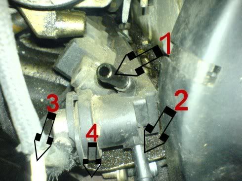
2 - Fuel rail, which is in and which return (1or2 see pics).
Where should the vacuum T piece go (3).
What is the other small exiting pipe beneath this pressure/vacuum bit go not seen in pic (4).
http://i196.photobucket.com/albums/aa283/timbrabants/Fuelrail.jpg
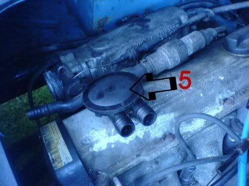
3 - What should this ?breather connection (5) be connected to?
http://i196.photobucket.com/albums/aa283/timbrabants/Breather.jpg
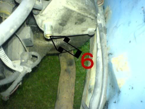
4 - Opposite end of intake manifold, (6) what pipe should go here? Is it the brake vacuum servo pipe?
http://i196.photobucket.com/albums/aa283/timbrabants/endofintake.jpg
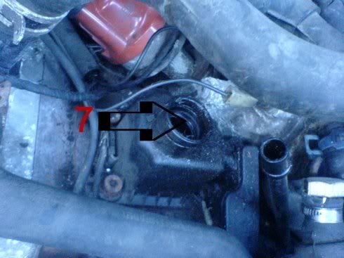
5 - What goes into here (7)? Should it be a sensor of some sort?
http://i196.photobucket.com/albums/aa283/timbrabants/sensorlocationmaybe.jpg
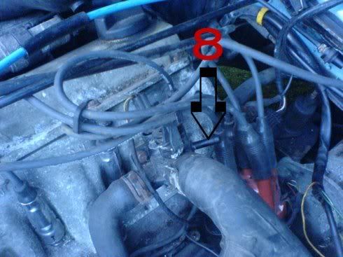
6 - What pipe goes on here (8)? Is it from the coolant expansion tank cap?
http://i196.photobucket.com/albums/aa283/timbrabants/returnfromexpansiontankcapmaybe.jpg
Many thanks in advance if you've made it to the end of this long post firstly, and secondly if you are able to offer any advice please!
AndySimpson:
1 fuel in 2 fuel out 3 connects to inlet manifold, other pipe could be mfa or ecu 5 should connect to no 7 and then onto the pipe near the throttle in the pic. 6 brake servo 8 would go to header tank in a golf, block it off for a t3.
Lambda sensor will be required.
timot25: Ah ha Thank you.
The intake pipe that fits on to the throttle body has a hole to accept the pipe next to it, but also has another hole which I guess number 5 might connect to too. I'm sure a sensor of some sort must be involved at number 7 as it has a large circlip type thing for it. I may be a bit stuffed with regard to the Lambda sensor as there is nowhere on the exhast manifold to put one. Is there an easy way round this?
There is nowhere on the ECU for a vacuum pipe and I don't know what an mfa is with regard to number 3!
AndySimpson:
No 5 connects on the rubber pipe between throttle and air flow meter.
N0 7 just has a pipe which comes out and instantly reduces in size.
Lambda sensor is best in exhaust front pipe as near to manifold as possible to get nice and hot.
The mfa is the display on the dash which tells lies about mpg.
Exhaust pipe with lambda sensor boss about £30?
Other Info
Engine code on block might be stamped near distributor on flat smooth boss.. forward of dizzie below cyl 3 ?